Preferred White Water rack layout
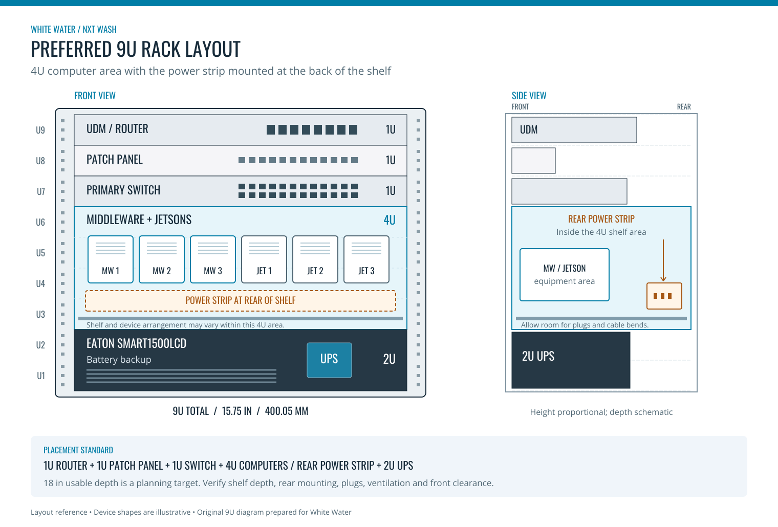
9U rack diagram: router, patch panel, switch, 4U middleware/Jetson area with rear power strip, and 2U UPS.
Preferred arrangement
Reserve 4U for the middleware and Jetsons. Arrange the computers and shelves within this area to suit the installation. The selected battery backup is the Eaton Tripp Lite SmartPro SMART1500LCD, a 2U unit.
The layout reserves 9U of rack space: 1U each for the router, patch panel and primary switch; 4U for middleware/Jetsons; and 2U for the UPS. Mount the power strip at the back of the middleware/Jetson shelf, inside the 4U computer area.
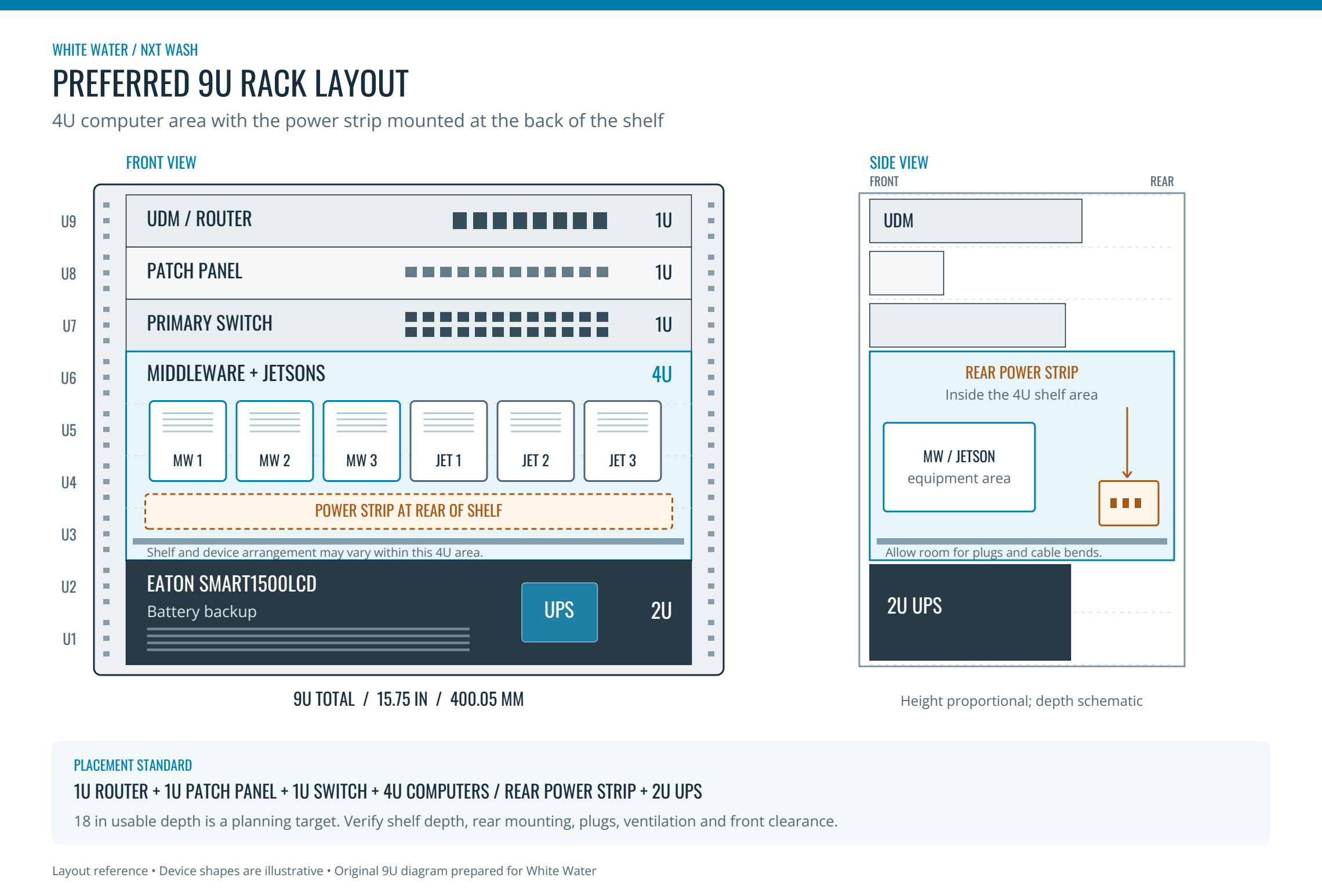
Open the full-size 9U diagram · Open the scalable SVG. Vertical sections follow the U allocations. Device shapes and side-view depths are illustrative; the drawing does not establish shelf part numbers or exact cable clearances.
Rack-space allocation
| Order, top to bottom | Equipment | Allocated height |
|---|---|---|
| U9 — top | UDM / router | 1U |
| U8 | Patch panel | 1U |
| U7 | Primary switch | 1U |
| U6–U3 | 3 middleware computers and 3 Jetsons; power strip at the back of the shelf, within this area | 4U |
| U2–U1 — bottom | Eaton Tripp Lite SMART1500LCD battery backup | 2U |
| Total | Preferred equipment allocation | 9U |
The power strip uses the rear of the 4U computer area and does not receive an additional U allocation. Arrange the devices and shelves within that area to suit the installation. Keep outlets accessible and preserve space for feet, vents, power adapters and cable bends. The 9U allocation is 400.05 mm / 15.75 inches of nominal mounting height, not the external height of the cabinet.
What a rack unit means
1U = 44.45 mm / 1.75 inches of nominal rack height. Middleware dimensions are 127.1 mm upright and 42.8 mm flat. Within the 4U computer area, use upright devices on a suitable shelf or flat devices on separate shelves, provided each device has adequate ventilation and cable clearance. Upright placement exceeds 2U (88.9 mm); flat placement nearly fills 1U, leaving only 1.65 mm before shelf thickness and clearance. A 1U allocation alone does not establish adequate clear height for a flat device.
Airflow and cabling
Do not stack equipment. Support each device on its own mounting hardware or shelf surface and allow adequate airflow around all vents, following manufacturer clearances. Do not place anything directly on top of the rack. Terminate incoming network drops from elsewhere on site with keystone jacks, label their destinations, and use patch cables to connect them to the appropriate switch ports.
Battery backup dimensions
| SMART1500LCD specification | Value |
|---|---|
| Rack height | 2U / 3.5 inches / 88.9 mm |
| Chassis depth | 10.5 inches / 266.7 mm |
| Chassis width | 17.25 inches / 438.15 mm |
| Weight | 30 lb |
Eaton product specifications. Account for this weight and the rest of the equipment when selecting the rack and mounting hardware. Keep the UPS at the bottom as shown in the preferred layout.
Battery backup identification photos
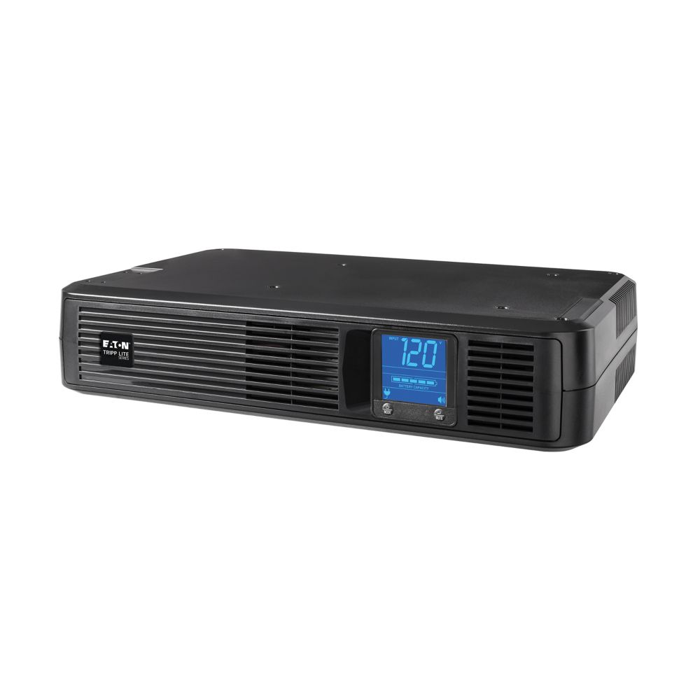
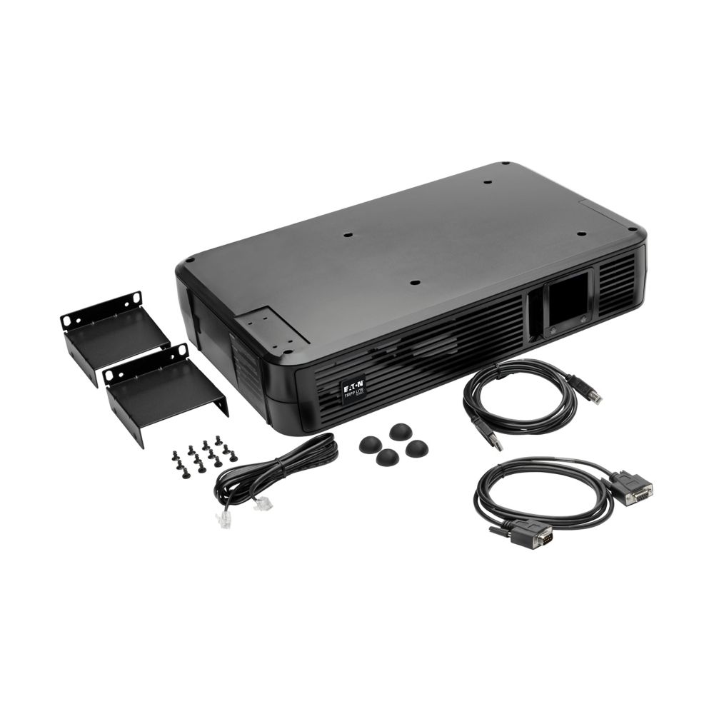
Open the battery backup equipment page.
Depth planning with the power strip behind the computer shelf
The router dimensions match the UDM-Pro: 442.4 mm wide × 43.7 mm high × 285.6 mm deep, a 1U device. Its chassis is 18.9 mm deeper than the selected UPS chassis.
The primary switch measures 442 mm wide × 285 mm deep × 44 mm high (17.4 × 11.2 × 1.7 inches). Its height fits the 1U allocation and its depth is almost identical to the UDM. Use the appropriate rack-mount ears for the 19-inch rack.
The power strip sits behind the middleware/Jetson shelf. Check each rack level separately:
| Rack area | Depth to allow |
|---|---|
| Router | UDM chassis: 285.6 mm / 11.24 inches, plus connected cables and clearance. |
| Primary switch | Switch chassis: 285 mm / 11.22 inches, plus connected cables and clearance. At 18 inches of usable depth, about 172 mm / 6.8 inches remains beyond chassis depth; confirm rail positions and front/rear plug clearance. |
| Computer shelf and rear power strip | Actual shelf/device depth plus the rear strip's intrusion, power adapters, connected plugs and cable bends. Measure the chosen arrangement. |
| Battery backup | UPS chassis: 266.7 mm / 10.5 inches, plus connected plugs and cable access. |
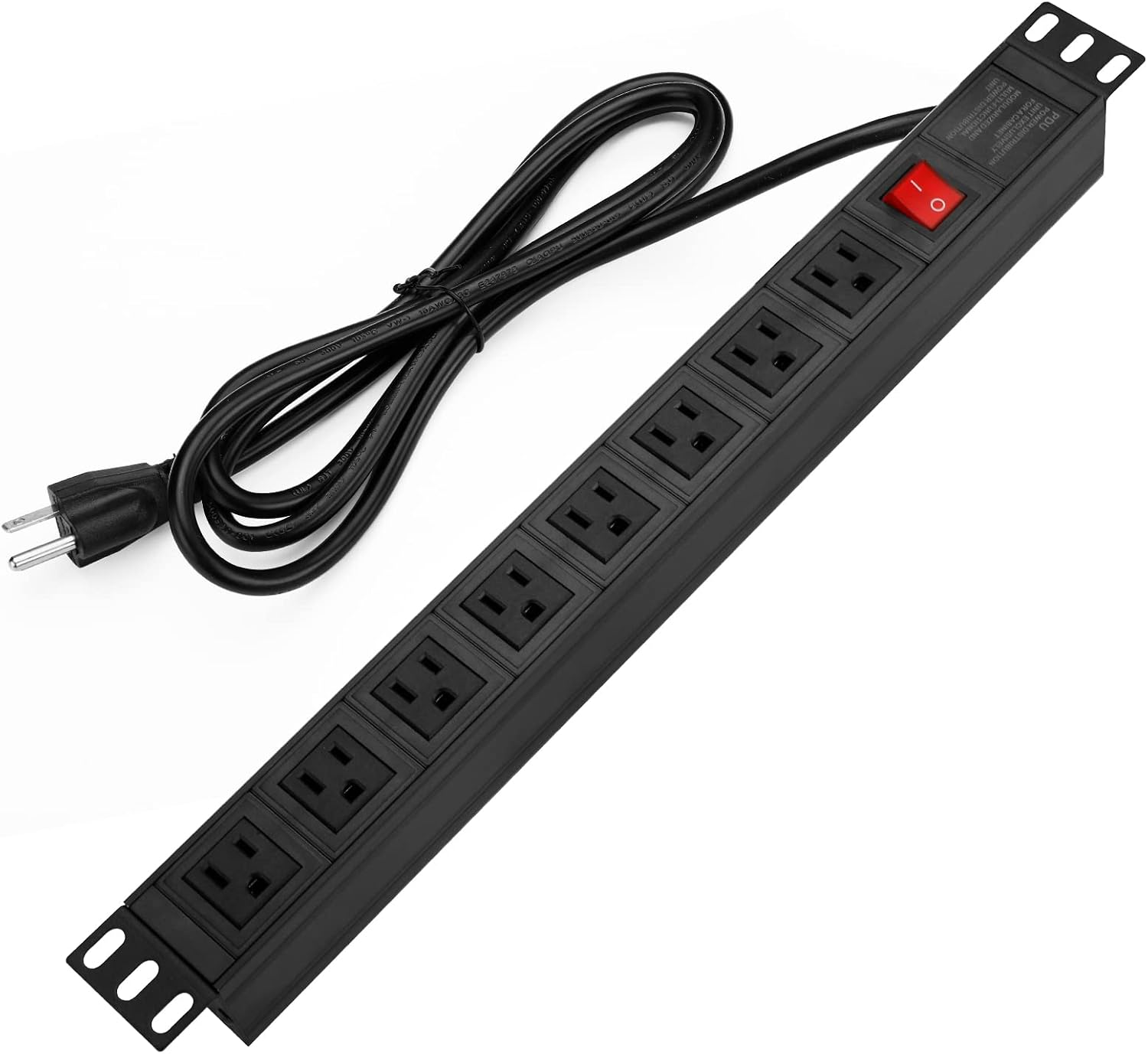
18 inches / 457.2 mm of usable internal depth is a planning target, pending the complete shelf and plugged-in strip arrangement. The strip dimensions are 19.31 inches long × 3.15 inches wide. If 3.15 inches is its front-to-back intrusion when mounted, it uses 80.01 mm at the rear; the available depth in front of it still needs to accommodate the actual computers, shelf and cables. Middleware height alone does not establish its installed depth.
View the power-strip photo. It shows mounting tabs and the outlet arrangement; verify mounting-hole fit, orientation and plug clearance with the selected shelf/rack. Confirm usable internal depth and rail positions, plus front network-plug/door clearance, rather than relying on the cabinet's outside depth.
Remaining installation details
Shelf/bracket part numbers, rear-strip mounting details, final depth/clearances, total load and required battery runtime still depend on the final equipment arrangement. The network's device addresses and ports remain in the network map.