White Water 24-port network map
Updated White Water network diagram, address ranges and switch-port reference.
Site network map
Use this standard address plan and port map alongside the current site information in NXT Wash Admin.
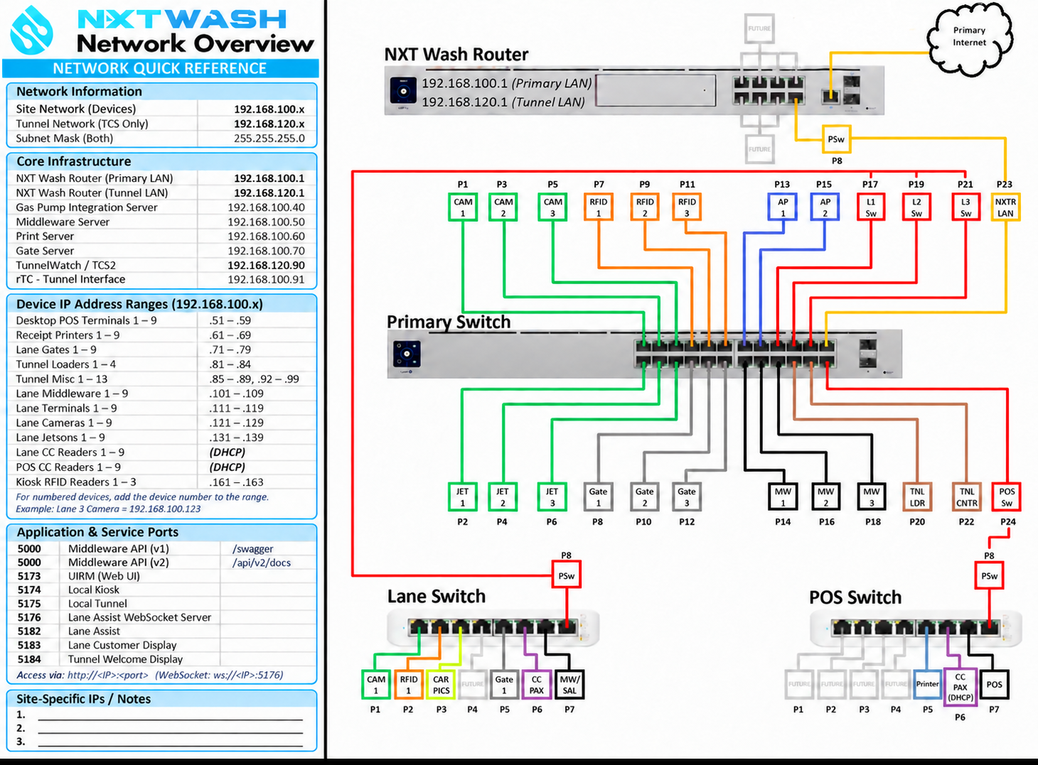
Open the full-size network diagram. For copyable service URLs, see Local application endpoints.
Network address plan
| Network | Address range | Router address | Subnet mask |
|---|---|---|---|
| Site devices / primary LAN | 192.168.100.x |
192.168.100.1 |
255.255.255.0 |
| Tunnel LAN — TCS only | 192.168.120.x |
192.168.120.1 |
255.255.255.0 |
Confirm site-specific addresses in NXT Wash Admin before applying this plan.
Core infrastructure addresses
| Device or service host | Planned IP address |
|---|---|
| NXT Wash router — primary LAN | 192.168.100.1 |
| NXT Wash router — tunnel LAN | 192.168.120.1 |
| Gas pump integration server | 192.168.100.40 |
| Middleware server | 192.168.100.50 |
| Print server | 192.168.100.60 |
| Gate server | 192.168.100.70 |
| TunnelWatch / TCS2 | 192.168.120.90 |
| rTC — tunnel interface | 192.168.100.91 |
The rTC entry applies at sites using that controller. The map places it on the site-device LAN. The separate TCS tunnel LAN and 192.168.120.90 entry apply to TunnelWatch / TCS2. Use the installed controller's recorded address and switch profile.
For dual-adapter TunnelWatch systems, 192.168.120.90 identifies the external connection. Preserve the protected internal adapter at 192.168.121.90; see TunnelWatch network details.
Device address ranges
Every fixed range in this table uses the 192.168.100 prefix. The middleware server at .50 is separate from the lane middleware range .101–.109.
| Device group | Numbered devices | Last octet / assignment |
|---|---|---|
| Desktop POS terminals | 1–9 | .51–.59 |
| Receipt printers | 1–9 | .61–.69 |
| Lane gates | 1–9 | .71–.79 |
| Tunnel loaders | 1–4 | .81–.84 |
| Tunnel miscellaneous devices | 1–13 | .85–.89, then .92–.99 |
| Lane middleware | 1–9 | .101–.109 |
| Lane terminals | 1–9 | .111–.119 |
| Lane cameras | 1–9 | .121–.129 |
| Lane Jetsons | 1–9 | .131–.139 |
| Lane credit-card readers | 1–9 | DHCP |
| POS credit-card readers | 1–9 | DHCP |
| Kiosk RFID readers | 1–3 | .161–.163 |
Within each contiguous numbered range, device 1 uses the first address. For example, lane 3 camera = 192.168.100.123, and lane 3 middleware = 192.168.100.103. The miscellaneous range is split; record those assignments explicitly. For card readers, use the current DHCP assignment in the site's device record.
Primary switch legend
| Ports | Diagram labels | Purpose |
|---|---|---|
| 1 / 3 / 5 | CAM 1 / 2 / 3 | Lane recognition cameras |
| 2 / 4 / 6 | JET 1 / 2 / 3 | Recognition processing devices |
| 7 / 9 / 11 | RFID 1 / 2 / 3 | Tag readers |
| 8 / 10 / 12 | Gate 1 / 2 / 3 | Lane gates |
| 13 / 15 | AP 1 / 2 | Wireless access points |
| 14 / 16 / 18 | MW 1 / 2 / 3 | Middleware computers |
| 17 / 19 / 21 | L1 / L2 / L3 Sw | Lane-switch uplinks |
| 20 | TNL LDR | Tunnel loader |
| 22 | TNL CNTR | Tunnel-controller connection; VLAN 120 for the TCS tunnel LAN |
| 23 | NXTR LAN | NXT Wash router LAN uplink; router port 8 in the diagram |
| 24 | POS Sw | POS-switch uplink |
Lane switch legend
| Port | Diagram label | Connection |
|---|---|---|
| 1 | CAM 1 | Lane recognition camera |
| 2 | RFID 1 | RFID reader |
| 3 | CAR PICS | Car Pics camera |
| 4 | FUTURE | Reserved for future use |
| 5 | Gate 1 | Lane gate |
| 6 | CC PAX | Card reader |
| 7 | MW/SAL | Middleware / sales device |
| 8 | PSw | Uplink to the primary switch |
On the documented lane switch, only ports 1–4 supply PoE. Verify the installed model and power budget.
POS switch legend
| Port | Diagram label | Connection |
|---|---|---|
| 1–4 | FUTURE | Reserved for future use |
| 5 | Printer | POS receipt printer |
| 6 | CC PAX (DHCP) | POS card reader |
| 7 | POS | POS terminal |
| 8 | PSw | Uplink to primary-switch port 24 |
Cutover dependencies
The White Water installation guide identifies loader port 20 and controller port 22. Confirm the installed controller's port profile before connecting it. The diagram's port labels identify the equipment connections; match actual cable paths to the site's installation record.
Self-install planning references
Use the preferred rack layout for equipment placement and the self-install readiness checklist for preconfiguration, no-cut mounting, training and missing configuration steps. The glossary explains device and software terms.