Troubleshooting
XPT Imager Barcode Reader (XP02325)
Tools needed:
#1 Phillips screwdriver
*Caution: Turn off the XPT before modifying any wiring connections.
1. Check for any warning or error messages in maintenance mode.
a. Unlock the XPT main door. The security login screen appears.
b. Log in to security. The Main Status Screen appears.
c. If the status of the Barcode Reader is anything other than OK, skip to step 6.
2. Verify that the red lights are visible in the imager barcode reader exit window.
a. From the Main Status Screen of maintenance mode, press the Enable & Test Hardware button. The Enable & Test Hardware screen appears.
b. Press the Barcode Reader button. The Barcode Reader screen appears.
c. There should be red lights that appear in the imager barcode reader exit window as shown below. Note: The imager assembly provides left and right side illumination panels. Pay close attention when checking for the red lights and ensure that both panels are illuminated.
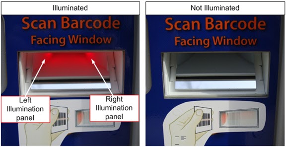
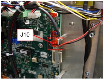
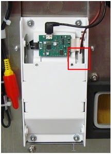
d. If no light is present, or if only the left or right side is illuminated, verify the illumination power cable is securely fastened to the connector inside the imager barcode reader and to the J10 connector on the display I/O board.
i. Perform step 6.b. to remove the imager barcode reader cover plate.
ii. Verify the cables are connected as shown in the images below.
3. Test the reader with a barcode printed in maintenance mode.
a. From the Main Status Screen of maintenance mode, press the Enable & Test Hardware button. The Enable & Test Hardware screen appears.
b. Press the Receipt Printer button. The Receipt Printer screen appears.
c. Press the Print Test Pattern button. The XPT prints a test receipt containing a barcode.
d. Press the Exit button. The Enable & Test Hardware screen re-appears.
e. Press the Barcode Reader button. The Barcode Reader screen appears.
i. Scan the barcode. If the barcode reader is working properly, TESTPATTERN appears in the Scan Data field after the barcode is scanned.
4. Clean the imager barcode reader exit window.
a. Clean the exit window with a soft, damp cloth using soap (such as Simple Green) and water. The exit window should be cleaned frequently to provide the imager camera a clear field of view.
i. Caution: Do NOT use abrasive materials or ammonia-based detergents on the window. Note: Many common glass cleaners contain ammonia.
b. Test the reader by returning to step 3. If the reader still does not work, proceed to the next step.
5. Enable and disable the imager barcode reader in maintenance mode.
a. While on the Barcode Reader screen in maintenance mode, press the Now Enabled (press to disable) button. The status of the barcode reader changes to Disabled.
b. Press the Now Disabled (press to enable) button. The status of the barcode reader changes to OK.
c. Test the reader by returning to step 3. If the reader still does not work, proceed to the next step.
6. Reseat the USB cable connection from the imager barcode reader to the carrier board assembly.
a. With the XPT main door open, turn the power off using the main power switch located on the back wall on the right side of the XPT case.
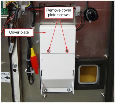
b. Remove the imager barcode reader cover plate.
i. Loosen and remove the cover plate screws using a #1 Phillips screwdriver.
ii. Remove the cover plate.
c. Disconnect the USB cable from the imager decoder board and reconnect it.
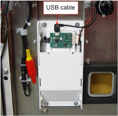
d. XPT 2012 units.
i. Follow the USB cable to the carrier board assembly, then disconnect and reconnect the cable there as well. Note: There are five or more USB ports on the carrier board, and the imager barcode reader may be connected to a different one than shown below.
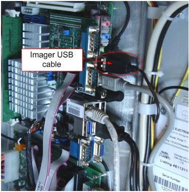
d. XPT 2012 units.
i. Follow the USB cable to the carrier board assembly, then disconnect and reconnect the cable there as well. Note: There are five or more USB ports on the carrier board, and the imager barcode reader may be connected to a different one than shown below.
7. Restart the XPT.
a. Open the XPT main door.
b. ocate the main power switch which is positioned on the back wall on the right side of the XPT main case.
c. Turn the power switch to the off position and verify the XPT turns off.
d. Wait 30 seconds and turn the power switch to the on position.
e. Test the barcode reader by returning to step 4. If it still does not work, proceed to the next step.
8. Barcodes are difficult to read in low lighting conditions.
a. Verify the red illumination is present in the exit window by referring to step 3.c.
b. Verify the area surrounding the XPT has adequate lighting.
i. The imager barcode reader operation is similar to that of a digital camera without a flash. Sufficient ambient light must be present in order for the barcode to be viewable.
9. Barcodes are difficult to read on mobile devices.
a. If the imager barcode reader has trouble reading barcodes on mobile devices (smart phones, tablets, etc.) the mobile device's screen brightness may be set too low.
i. Consider adding appropriate signage that advises customers to increase their screen brightness before attempting to scan a barcode at the XPT.
b. If the XPT is not installed under a canopy, sunlight could be causing glare on the mobile device screen.
i. Consider installing a canopy over the XPT.
10. Barcodes are difficult to read during bright sunlight, or at certain times of the day.
a. A canopy is highly recommended over the XPT to prevent sunlight glare on the imager barcode reader exit window.
11. Replacing the imager barcode reader.
a. If you have followed all the steps above and the imager barcode reader still does not work, contact the IT support team to order a replacement scanner and follow the replacement section for replacing the unit.
Replacing
Tools needed:
5/16" Nut driver
3/8" Nut driver
Flat head screwdriver
Phillips screwdriver
1. Turn off the XPT.
a. Unlock the XPT main door. The security login screen appears.
b. Log in to security. The Main Status Screen appears.
c. Open the XPT main door.
d. Turn the power off using the main power switch located on the back wall on the right side of the XPT case.
2. Prepare the imager barcode reader USB and power cables to be returned with the original hardware.
a. Remove the USB and power cables from the cable clips and disconnect from the display I/O board and carrier board.
i. Disconnect the power cable from J10 on the display I/O board.
ii. Disconnect the USB cable from the carrier board. Note: There are five USB ports on the carrier board, and the imager barcode reader can be connected to any one of them, so it may be necessary to trace the cable back to identify the correct one.
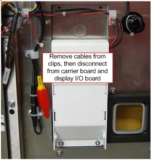
3. Remove the imager barcode reader cover plate.
a. Loosen and remove the cover plate screws using a #1 Phillips screwdriver.
b. Remove the cover plate.
4. Remove the USB and power cables from the slot in the side of the housing to gain access to the top right mounting nut.
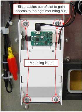
5. Remove the imager barcode reader from the XPT main door.
a. Loosen and remove the (4) mounting nuts using a 5/16" nut driver.
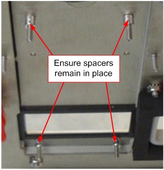
b. Carefully pull the imager barcode reader from the XPT main door and ensure the spacers remain in place on the studs.
6. Insert the replacement imager barcode reader.
a. Remove the cover plate from the replacement imager barcode reader, as was done in step 3 above.
b. Carefully install the replacement imager barcode reader on the main door and ensure its housing is fully seated against the spacers.
c. Hand-tighten the (4) 5/16" mounting nuts and verify the imager barcode reader housing is still seated evenly against the main door.
d. Finish tightening the mounting nuts with a 5/16" nut driver.
7. Route the imager barcode reader USB and power cables through the cable clips and reconnect to the carrier board and display I/O board.
a. Connect the USB cable to any unused USB port on the carrier board.
b. Connect the power cable to J10 on the display I/O board.
8. Replace the imager barcode reader cover plate.
a. Replace the cover plate and secure it to the housing with the Phillips screws.
9. Turn on the XPT and test the barcode reader operation.
a. Turn the power on using the main power switch located on the back wall on the right side of the XPT case.
b. After the XPT starts up, log in to security. The Main Status Screen appears.
c. Press the Enable & Test Hardware button. The Enable & Test Hardware screen appears.
d. Press the Barcode Reader button. The Barcode Reader screen appears.
e. Scan a barcode to verify proper operation.
f. Close and lock the XPT main door.
White Water guide · Download PDF ↗