XPT 5 Display Module Overview
Product: XPT 5 Display Module (XP11040), XPT 5+ Display Module (XP11045)
This topic describes the display module in an XPT 5 and XPT 5+.
The display module includes a touchscreen and LCD, and an I/O board that interfaces to all of the devices on the XPT main door.
The display module is considered a "sealed" unit, meaning that we should not try to remove any protective covers or disassemble the module – individual components are not field-replaceable.
When compared to previous generations of XPT, the display module is a single piece of hardware that replaces all of the following devices:
Display I/O assembly
Touchscreen assembly
Touchscreen controller
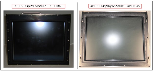
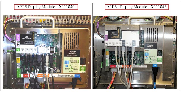
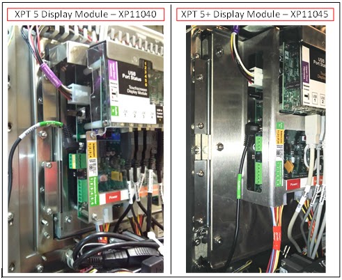
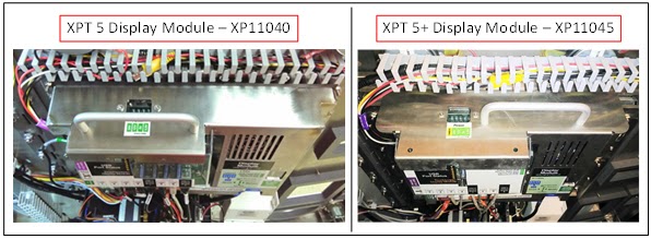
The difference between the XPT 5 and XPT 5+ display module is a 12.1” vs. a 15” display and touchscreen. Both module versions look nearly identical, other than a size difference, and therefore, most pictures and diagrams in this document show only one version.
Front
Back
Side
Top
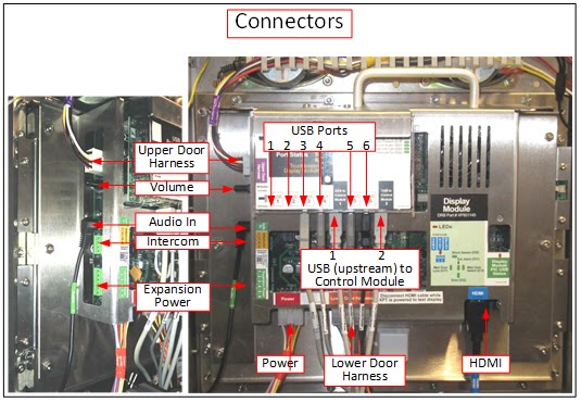
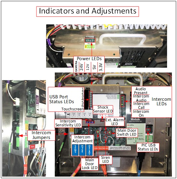
Connections and Indicators
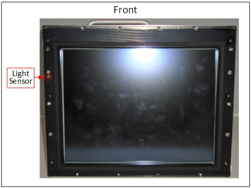
There are connection points and/or indicators on the back, side, and top of the display module. The light sensor is on the front of the display module.
Back/Side Connectors
Back/Side/Top - Indicators and Adjustments
Front
Connector Pinouts
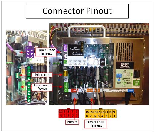
Upper Door Harness
Pin Description
1 Left Speaker+
2 Right Speaker+
3 Main Door Lock+
4 Camera Power (Isolated)-
5 Left Speaker -
6 Right Speaker-
7 Main Door Lock-
8 Camera Power (Isolated)+
Lower Door Harness
Pin Description
1 Imager Illumination Power (5V)
2 Card Dispenser 5V
3 Card Dispenser GND
4 Ultrasonic Prox GND
5 Printer Power GND
6 EMV Power GND
7 Help Switch Out
8 Help Switch LED+
9 Imager Illumination Power GND
10 Card Dispenser 24V
11 Ultrasonic Prox Signal
12 Ultrasonic Prox Power
13 Printer Power 24V
14 EMV Power 12V
15 Help Switch In
16 Help Switch LED-
Power
Pin Description
1 GND
2 GND
3 Shock Sensor Out
4 Siren Out
5 Door Lock Out
6 12V
7 24V
8 12V Battery
9 External Alarm Out
10 Door Switch In
Serviceable Fasteners
Maintenance
Clean the touchscreen with a soft, damp cloth using soap (such as Simple Green) and water.
*Warning: Do NOT use abrasive materials or ammonia-based detergents on the touchscreen. Note: Many common glass cleaners contain ammonia.
Replacing
*Warning: Turn off the XPT before modifying any power wiring connections.
An employee with security access must enter his or her employee information into the XPT after unlocking, but before opening, the main door. Failure to follow this procedure causes the alarm to sound.
Tools needed
11/32" nut driver
Procedure steps
1. Turn off the XPT.
a. Unlock the XPT main door. The security login screen appears.
b. Log in to security. The Main Status Screen appears.
c. Open the XPT main door.
d. Turn the power off using the switch on the front of the power module.
2. Tilt the receipt printer mechanism out of the way.
a. Squeeze and hold the metal lever on the left side of the print head. Note: The lever only travels a very small distance, and may not feel like it has been activated properly. Tension on the paper will be released when properly activated.
b. Gently pull the paper through the rear of the printer mechanism.
c. Pull the right hinge pin to the rear position.
d. Tilt the printer mechanism to the left.
3. Disconnect all external cables from the display module.
4. Remove the display module.
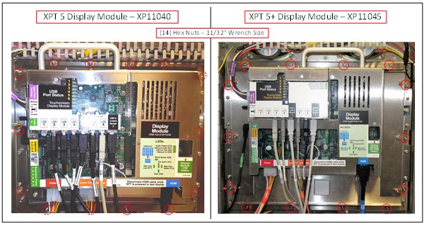
a. Loosen and remove the (14) hex nuts from around the perimeter of the module, using a 11/32" nut driver.
b. Slide the display module off of the studs on the main door.
5. Install the replacement display module.
a. Slide the replacement display module onto the studs on the main door.
b. Tighten the (14) hex nuts around the perimeter of the module using a 11/32" nut driver.
6. Reconnect external cables to the display module.
7. Return the receipt printer to the normal operating position.
a. Tilt the printer mechanism to the right.
b. Push the right hinge pin forward until it locks into place.
c. Feed receipt paper into the back of the receipt printer.
8. Turn on the XPT and log in to security.
a. Turn the power on using the switch on the front of the power module. The XPT starts up and the security login screen appears.
b. Log in to security. The Main Status Screen appears.
9. Test the display module operation.
a. Verify that the following devices report a status of OK on Main Status Screen.
ii. Mag Card Reader
iii. NFC Reader
iv. Receipt Printer
v. Card Dispenser (if installed)
b. Press the Help button and verify the Main Status Screen Help screen appears.
c. Press the Help button again to return to the Main Status Screen.
10. If the XPT is connected to an intercom system, it may be necessary to adjust the intercom settings on the display module.
a. Refer to the "XPT Intercom Operation and Adjustment" topic for more information on these adjustments.
11. Close and lock the XPT main door.
XPT 5+:
1. Turn off the XPT.
a. Unlock the XPT main door. The security login screen appears.
b. Log in to security. The Main Status Screen appears.
c. Open the XPT main door.
d. Turn the power off using the switch on the front of the power module.
2. Disconnect all external cables from the display module.
3. Remove the display module fasteners.
a. Loosen and remove the (14) hex nuts from around the perimeter of the module, using a 11/32" nut driver, while holding the display module handle, so that it's supported when the last nut is removed.
b. Note: Do not remove the (6) additional hex nuts that secure the module cover.
4. Tilt the receipt printer mechanism out of the way.
a. Squeeze and hold the metal lever on the left side of the print head. Note: The lever only travels a very small distance, and may not feel like it has been activated properly. Tension on the paper will be released when properly activated.
b. Gently pull the paper through the rear of the printer mechanism.
c. Pull the right hinge pin to the rear position.
d. Tilt the printer mechanism to the left.
5. Slide the display module off the studs on the main door.
6. Install the replacement display module.
a. Slide the replacement display module onto the studs on the main door and finger-tighten one of the hex nuts near the top of the module to temporarily hold it in place.
7. Return the receipt printer to the normal operating position.
a. Tilt the printer mechanism to the right.
b. Push the right hinge pin forward until it locks into place.
c. Feed receipt paper into the back of the receipt printer.
8. Reconnect external cables to the display module.
9. Replace the remaining (13) hex nuts around the perimeter of the module and tighten all (14) hex nuts using a 11/32" nut driver.
10. Turn on the XPT and log in to security.
a. Turn the power on using the switch on the front of the power module. The XPT starts up and the security login screen appears.
b. Log in to security. The Main Status Screen appears.
11. Test the display module operation.
a. Verify that the following devices report a status of OK on Main Status Screen.
ii. Mag Card Reader
iii. NFC Reader
iv. Receipt Printer
v. Card Dispenser (if installed)
b. Press the Help button and verify the Main Status Screen Help screen appears.
c. Press the Help button again to return to the Main Status Screen.
12. If the XPT is connected to an intercom system, it may be necessary to adjust the intercom settings on the display module.
a. Refer to the "XPT Intercom Operation and Adjustment" topic for more information on these adjustments.
13. Close and lock the XPT main door.
Troubleshooting
*Warning: Turn off the XPT before modifying any power wiring connections.
An employee with security access must enter his or her employee information into the XPT after unlocking, but before opening, the main door. Failure to follow this procedure causes the alarm to sound.
The 12V and/or 24V LEDs are off
1. Verify the module power harness is connected to the bottom of the display module and the front of the power module.
2. Check the power LEDs on the control module.
a. If the LEDs are off, troubleshoot the power module.
b. If the LEDs are on:
i. Turn the XPT power off using the switch on the front of the power module.
ii. Disconnect the lower door harness from the display module.
iii. Turn the XPT power on.
iv. If the power LEDs on the display module are now on, there is likely a problem with one of the devices that connects to the lower door harness:
Turn the XPT power off.
Reconnect the lower door harness.
Disconnect all devices from the harness except for one, turn the power on, and determine if the LED turns off.
Repeat this process by connecting the remaining devices to the lower door harness, one at a time, to isolate the faulty device.
v. If the power LEDs on the display module are still off, replace the display module.
The 3.3V or 5V LEDs are off, but the 12V LED is on
1. The display module is faulty and should be replaced.
Display module status in maintenance mode indicates an error
1. Reset the display module in maintenance mode.
a. From the Main Status Screen, press the Enable & Test Hardware button. The Enable & Test Hardware screen appears.
b. Press the Security Devices button. The Security Devices screen appears.
c. Press the Reset Display Module button. The display module resets.
2. Restart the XPT.
a. Unlock the XPT main door. The security login screen appears.
b. Log in to security. The Main Status Screen appears.
c. Open the XPT main door.
d. Turn the power off using the switch on the front of the power module.
e. Wait a minimum of 10 seconds.
f. Turn the power back on.
Display module and any other device connected to the display module USB hub ports 5 or 6 indicates a communication-related error status in maintenance mode
1. Restart the XPT.
a. Unlock the XPT main door. The security login screen appears.
b. Log in to security. The Main Status Screen appears.
c. Open the XPT main door.
d. Turn the power off using the switch on the front of the power module.
e. Wait a minimum of 10 seconds.
f. Turn the power back on.
2. Adjust the USB cable connection.
a. Disconnect and reconnect the (2) USB cables between the display module USB hub and the USB ports on the front of the control module, and then restart the XPT.
b. Connect the (2) USB cables between the display module USB hub and the control module to different USB ports on the front of the control module, and then restart the XPT.
c. Swap the position of the (2) USB cables from the control module at the USB Type-B ports on the display module USB hub, labeled "USB to Control Module 1" or "USB to Control Module 2", and then restart the XPT.
d. If the status of the display module and any device connected to display module USB hub ports 5 or 6 changes to OK, but the devices connected to hub ports 1-4 indicate a communication-related error in maintenance mode, there is likely a problem with the USB cable, and it should be replaced.
The Main Door Lock is not indicating the proper status in maintenance mode when unlocked/locked
1. Look at the Main Door Lock LED on the front of the display module while locking/unlocking the main XPT door lock.
a. LED turns off when unlocked, and on when locked (opposite of normal operation).
i. Verify the connectors from the wire harness are connected to the two outside terminals on the switch; the middle terminal is not used.
b. LED remains off.
i. Temporarily touch a jumper wire between the two terminals on the switch that connect to the upper door harness.
If the LED turns on, the switch is faulty and needs to be replaced.
c. LED remains on.
i. Manually depress the switch arm.
If the LED turns off, gently bend the switch arm towards the lock cylinder so it will make greater contact with the lock plug when inserted.
If the LED does not turn off, disconnect the upper door harness from the display module.
If the LED turns off, the switch is faulty and needs to be replaced.
If the LED does not turn off, the display module needs to be replaced.
The Main Door Switch is not indicating the proper status in maintenance mode when opened/closed
1. Troubleshoot the XPT power module using the "XPT 5 Power Module" topic.
The speakers are not playing XPT audio
1. Verify the customer has SiteWatch version 23.9.0.674 or later.
a. If the customer does NOT have SiteWatch version 23.9.0.674 or later, they need to be upgraded to a more recent version of SiteWatch.
b. If the customer does have SiteWatch version 23.9.0.674 or later, proceed to step 2.
2. Press the Play Test Audio button on the Main Status Screen in maintenance mode.
a. If audio can be heard, the problem is likely with SiteWatch media configuration.
b. If audio cannot be heard, verify the volume knob on the left side of the display module is turned up.
c. When viewing the left side of the display module, the volume knob should be turned clockwise to increase the volume.
3. Verify cable connections.
a. Verify the audio cable is connected between the left side of the display module and the top of the control module.
b. Verify the upper door harness connector is fully seated on the left side of the display module.
c. Verify the upper door harness is connected to the left and right speakers.
4. Verify the display module is not in intercom audio mode.
a. The Intercom On LED should be off.
b. If it is on, refer to the adjustment instructions in the "XPT Intercom Operation and Adjustment" topic.
5. Verify the 24V LED is on.
Display module LCD shows a test pattern image with the text “No Signal
The right half of the display is not initialized during a self-test, and could display a series of vertical bars in various colors – this does not indicate a problem.
1. Restart the XPT.
a. Unlock the XPT main door. The security login screen appears.
b. Log in to security. The Main Status Screen appears.
c. Open the XPT main door.
d. Turn the power off using the switch on the front of the power module.
e. Wait a minimum of 10 seconds.
f. Turn the power back on.
2. Disconnect and reconnect the HDMI cable between the bottom of the display module and the front of the control module.
3. Verify the motherboard is receiving 12V power and is turned on.
a. Verify the 12V LED on the control module is on.
b. If the 12V LED is off, see the "The 12V and/or 24V LEDs are off" troubleshooting step in the "XPT 5 Control Module" topic.
c. If the Motherboard Power LED (green) on the control module is not lit, press and release the MB Pwr (Motherboard Power) button on the front of the control module.
4. Replace the HDMI cable.
5. Replace the control module.
The display is dark instead of displaying the XPT.exe
1. Hold the Help button for a minimum of 5 seconds.
a. If the Main Status Screen appears, then the display module is working properly, and the dark screen is caused by SiteWatch configuration.
2. Restart the XPT.
a. Unlock the XPT main door. The security login screen appears.
b. Log in to security. The Main Status Screen appears.
c. Open the XPT main door.
d. Turn the power off using the switch on the front of the power module.
e. Wait a minimum of 10 seconds.
f. Turn the power back on.
3. Verify the display module is powered.
a. Verify the display module 3.3V, 5V, 12V, and 24V LEDs are on.
b. If any of the LEDs are off, see the appropriate troubleshooting step in this topic.
4. Disconnect the HDMI cable from the bottom of the display module.
a. If the display shows a test pattern image on the left side with the text No Signal, see the troubleshooting steps for that condition above.
The touchscreen is not recognizing touch properly
*Gloves can diminish touchscreen sensitivity.
1. Restart the XPT.
a. Unlock the XPT main door. The security login screen appears.
b. Log in to security. The Main Status Screen appears.
c. Open the XPT main door.
d. Turn the power off using the switch on the front of the power module.
e. Wait a minimum of 10 seconds.
f. Turn the power back on.
2. Adjust the USB cable connection.
a. Disconnect and reconnect the (2) USB cables between the display module USB hub and the USB ports on the front of the control module, and then restart the XPT.
b. Connect the (2) USB cables between the display module USB hub and the control module to different USB ports on the front of the control module, and then restart the XPT.
c. Swap the position of the (2) USB cables from the control module at the USB Type-B ports on the display module USB hub, labeled "USB to Control Module 1" or "USB to Control Module 2", and then restart the XPT.
d. If the touchscreen starts working, but the devices connected to hub ports 1-4 indicate a communication-related error in maintenance mode, there is likely a problem with the USB cable, and it should be replaced.
3. Calibrate the touchscreen.
a. Log in to maintenance mode.
b. On the Main Status Screen, press the Calibrate Touch button.
c. Pressing this button opens a touch calibration utility on the screen.
d. The crosshair first appears in the top left corner of the screen. After it is pressed, it moves to another point on the screen. Continue pressing the crosshair until the calibration is complete.
e. Once the touch calibration is complete, the XPT reboots.
f. If the touchscreen is not responding at all, establish a Remote Desktop connection to the XPT (verify Remote Desktop is set for 1024 x 768 screen resolution), log in to maintenance mode, click Calibrate Touch, and then click the End Remote Desktop Session.bat shortcut in the Windows Start Menu to return the local XPT to the calibration screen.
4. Test the touchscreen.
a. Log in to maintenance mode.
b. On the Main Status Screen, press the Test Touch button.
c. Pressing this button opens a screen of circles used to test the touchscreen.
d. Touch or drag your finger across the screen to see if any areas do not recognize touch.
e. When a touch inside a circle is recognized, its color changes from black to green.
f. If any areas of the touchscreen do not recognize touch after proper calibration, the display assembly should likely be replaced.
g. Press and hold the Help button to exit the screen.
The intercom system is not operating correctly
1. Refer to the "XPT Intercom Operation and Adjustment" topic.
The display resolution is incorrect after a control module or SSD swap
1. Verify the SSD image revision is 9.7.1 or later.
a. Locally: Look at the label on the side of the SSD.
b. Remotely: In Windows, navigate to Control Panel\All Control Panel Items\System and look for the revision number within the Model information.
White Water guide · Download PDF ↗