Goal: Cover the concepts behind the XPT/SAL lane process, understanding the gates and loops and how they tie into the sales and queue experience.
Loop Definition and Types
The detection of the customer vehicle at various positions in the sales line is based on several ‘loops’ in the asphalt that detect the presence of a vehicle. A loop is a pair of twisted copper wires that are literally ‘looped’ in a square pattern several times under the ground creating a small magnetic field once electricity is applied to the wire. When a vehicle or large piece of metal comes in close proximity to the loop wire the magnetism pulls the wire closer together and increases the frequency of the signal running along the loop and thus a vehicle is detected. Each loop wire connects to the lane’s gate, and the gate is responsible for controlling what happens when a loop is triggered.
Below is a render of a typical lane configuration highlighting the 3 main loops we have at our locations:
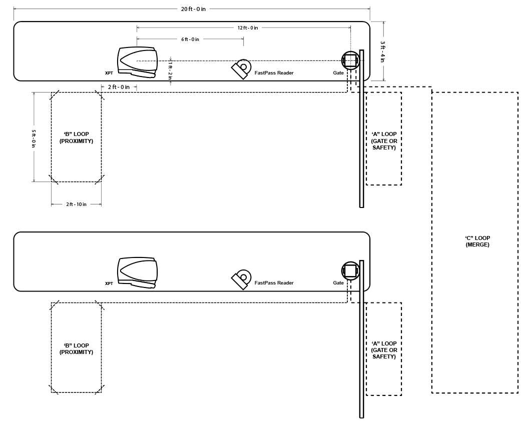
*Typical Loop Configuration in a Dual XPT Layout
Starting from left to right, let’s define the purpose and function of each loop:
The ‘B’ Loop, also known as the ‘Proximity’ Loop, is the first loop a vehicle comes in contact with as the customer approaches the XPT. Triggering this loop begins the sale at the XPT and will both move the sale to the main menu and activate the FastPass reader at the same time. It is during this approach that the tag is read typically just before a vehicle stops so that if the customer is an unlimited member the gate will go up quickly and they won’t need to come to a full stop.
*Note that if the B loop fails to trigger the sale will not automatically start and the FastPass reader will not turn on, this is the number one cause of read failures and if you notice consistent failed reads check the gate to be sure a vehicle is being detected by loop B (we will cover this later).
The ‘A’ Loop, also known as the ‘Gate’ or ‘Safety’ Loop, is the second loop the vehicle comes into contact with and is located just past the gate arm in the lane. This loop acts as a detector to make sure nothing metal is under the gate before it closes, therefore vehicles (not human heads though, be careful!) must be clear of the loop before the gate is allowed to close. If you have gates coming down on vehicles then likely this loop is not functioning properly and should be checked/calibrated (calibration steps later).
Loop A is responsible for putting vehicles into the wash queue, if Loop A fails to trigger that the gate has gone up and down for the vehicle you may see a gate busy signal from Loop A.
The ‘C’ Loop, or ‘Merge’ Loop, is the loop (sometimes singular or one in each lane) beyond the gates that acts as a merge area for the vehicles entering the queue. The goal of the C Loop is to keep more than one vehicle from entering the wide area beyond the gates and causing either a traffic jam or vehicles out of order in the queue. Once a vehicle clears the merge zone it should be in an area that is too narrow to fit more than one car, and the gate for the next lane can then open letting a second vehicle through into the queue. Typically the merge loop is controlled by the first gate only.
Gate Control Overview
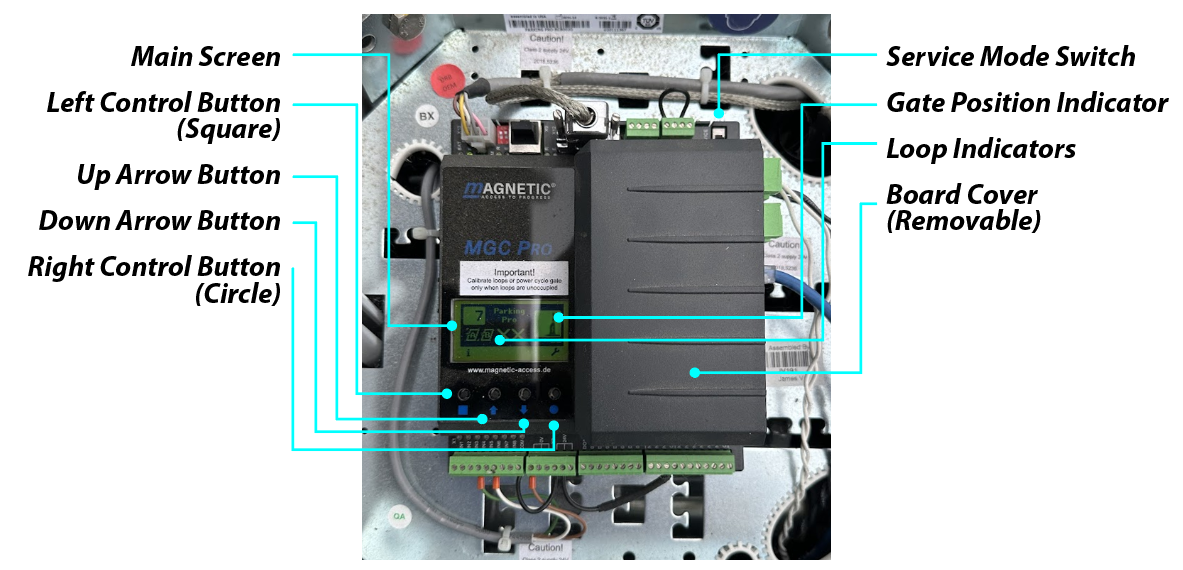
Inside the top of the gate is the control module and wiring for all the loops and the network connection. The control module consists of several hardware items:
The control module itself is the base of the unit and includes the screen, its control buttons and the main board of the gate for peripheral and network attachment.
Under the screen are 4 buttons: the Left (Square) control, the up and down buttons and the Right (Circle) control. These are used to navigate the menus of the gate to recalibrate and check the settings of the gate and its functions.
The screen should always have the number 7 in the upper left, this indicates it is operating in mode 7, the default mode we use.
The upper right of the screen shows the gate arm position, either up or down.
The bottom portion of the main screen shows the status of the individual loops, as pictures we see Loops A and B are idle and Loops C and D are not configured. If Loop A or B were active they would be blinking indicating a vehicle is in that position. Use this to troubleshoot loop detection issues.
On the main screen the far right button (circle) gets you into the menu options, a variety of functions and information is available as well as calibration functions.
The ‘Service Mode’ toggle switch on the upper right of the board allows you to take manual control of the gate functions from the control module and disables inputs from the loops and XPT while switched on.
On the right side of the control module is a plastic cover that can be removed if hardware needs to be replaced (an image below shows the control module with the cover removed).
The fist two slots on the right side are the ‘Gate Control Cards’, the top card controls the detectors for Loops A and B, the bottom of the two cards controls detectors C and D (where applicable).
The third card is the Ethernet card and is only connected to the network cable that runs to the XPT. These cards can be pulled and replaced with replacement cards if necessary, be sure power is turned off before moving any hardware on this board.
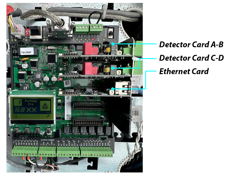
*Gate Control Module and Hardware
Gate and Loop Troubleshooting
Depending on the issue you are experiencing a loop calibration is advised before contacting IT or submitting a work order. Below are the scenarios where a recalibration should be performed.
FastPass reader is not activating - this indicates a problem with Loop B, the main screen should indicate with a flashing ‘B’ icon when a vehicle is present near the XPT. If it is not flashing then the B Loop (Detector A-B) needs re-calibrated and that will then activate the reader when a vehicle approaches or is sitting at the XPT.
Vehicles not showing up in the Tunnel Queue. Typically if you are seeing cars sent through the tunnel without getting any services you have what we call a ghost car. This occurs when the eye at the beginning of the tunnel is triggered to send a vehicle without the wash showing up in the queue, TunnelWatch by default sends a basic rinse in this situation, the cause is the A Loop is likely stuck on or off. Check to see if you have a ‘Gate Busy’ signal on the wash queue screen on the terminal controller or if the A Loop is flashing on the gate control module without a vehicle present at the gate.
Gates are not opening in other lanes after a vehicle is processed through an XPT. This could be caused by either the A Loop from one gate being stuck on or the C Loop detecting a vehicle when there is no vehicle in the merge zone. In either case you should refer to the gate screen to see if any indicators are flashing where there is no vehicle.
Gate Calibration
There are 3 ways to calibrate the gate and in each scenario you must make sure all loops are clear of vehicles before performing the recalibration.
The easiest way to calibrate a gate is to open the gate top and press and hold the 2 arrow buttons (middle buttons) for 2 seconds, this should reset the gate and prompt an automatic recalibration of the loops. Alternatively this function can be performed with the ‘Reset Gate’ button located on your terminal controller screen.
Power cycling the gate from the power button located under the front fascia of the gate base also forces a recalibration. This method takes the longest amount of time but may be the most reliable.
From the main menu, use the circle button to reach the options menu, from there navigate to either ‘Detector A-B’ or ‘Detector C-D’ and entering that menu and select ‘Recalibration’ to check mark it and exit to the main menu to trigger the recalibration of the loop you need fixed.
White Water guide · Download PDF ↗