XPT 5 Control Module
Product: XPT 5 Control Module w/SSD (XP11000)
This topic describes the control module in an XPT 5 and XPT 5+.
The control module includes a motherboard, SSD, and I/O boards that interface to the components in the main XPT case, and to external gates and third-party devices.
The control module is considered a "sealed" unit, meaning that we should not try to remove any protective covers or disassemble the module – individual components are not field-replaceable.
When compared to previous generations of XPT, the control module is a single piece of hardware that replaces all of the following devices:
Carrier board assembly
Wash I/O board
Misc. I/O board
*SSD can be replaced independent of the entire module
Pictures
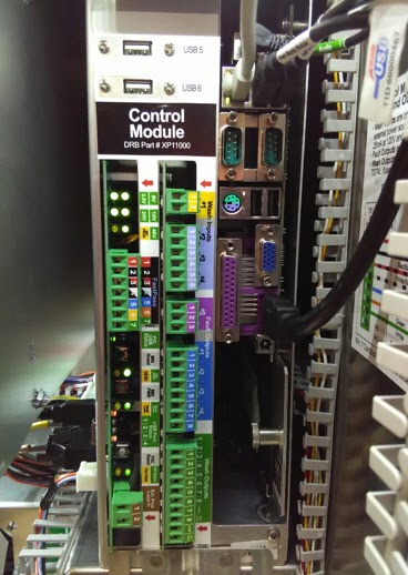
Front
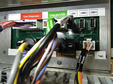
Side
Connections
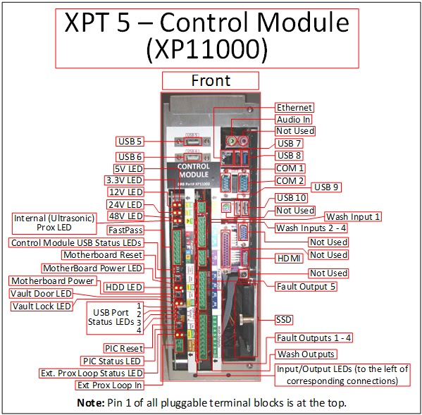
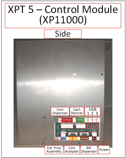
There are a number of connection points on the control module; both on the front and side of the module.
Connector Pinouts
Front
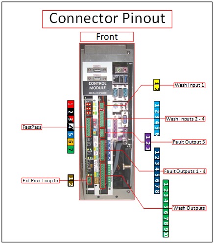
Connector Pinouts
FastPass
Pin Description
1 48VDC
2 GND
3 RTS
4 DTR
5 RXD
6 TXD
7 GND
Ext. Prox Loop In (opt.)
Pin Description
1 Ext. Prox Loop Lead
2 Ext. Prox Loop Lead
Wash Input 1
Pin Description
1 Input 1 - Hot
2 Input 1 - Neutral
Wash Inputs 2-4
Pin Description
1 Input 2 - Hot
2 Input 2 - Neutral
3 Input 3 - Hot
4 Input 3 - Neutral
5 Input 4 - Hot
6 Input 4 - Neutral
Fault Output 5
Pin Description
1 Fault Output 5 (Common)
2 Fault Output 5 (N/C)
3 Fault Output 5 (N/O)
Fault Outputs 1-4
Pin Description
1 Fault Output 1 (N/O)
2
3 Fault Output 2 (N/O)
4
5 Fault Output 3 (N/O)
6
7 Fault Output 4 (N/O)
8
Wash Outputs
Pin Description
1 Wash Output 1 (N/O)
2 Wash Output 2 (N/O)
3 Wash Output 3 (N/O)
4 Wash Output 4 (N/O)
5 Wash Output 5 (N/O)
6 Wash Output 6 (N/O)
7 Wash Output 7 (N/O)
8 Wash Output 8 (N/O)
9 Relay Output Common
10 Not Connected
Side
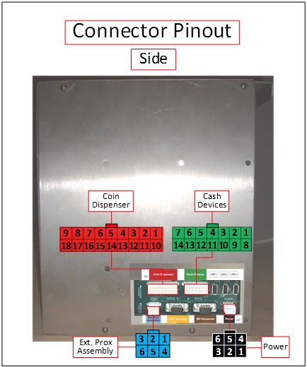
Coin Dispenser
Pin Description
1 Hopper 1 Run
2 Hopper 1 Out
3 Hopper 1 Coin Drop
4 Hopper 2 Run
5 Hopper 2 Out
6 Hopper 2 Coin Drop
7 Hopper 3 Run (Not Used)
8 Hopper 3 Out (Not Used)
9 Hopper 3 Coin Drop (Not Used)
10 GND
11 GND
12 Hopper 1 Reverse
13 GND
14 GND
15 Hopper 2 Reverse
16 GND
17 GND
18 Hopper 3 Reverse (Not Used)
Cash Devices
Pin Description
1 GND
2 GND
3 Not Connected
4 GND
5 GND
6 GND
7 GND
8 Vault Lock Switch
9 Vault Door Switch
10 Ultrasonic Prox Signal
11 Ultrasonic Prox Power
12 24VDC Bill Acceptor Power
13 24VDC Bill Dispenser Power
14 24VDC Coin Acceptor Power (Switched)
Ext. Prox Loop Assembly
Pin Description
1 24VDC
2 24VDC
3 GND
4 Loop Wire
5 Loop Wire
6 Loop Detect Signal
Power
Pin Description
1 GND
2 GND
3 12VDC
4 48VDC
5 24VDC
6 GND
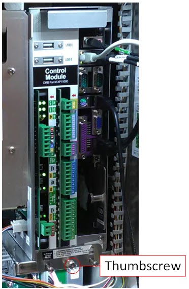
Serviceable Fasteners
Replacing
*Warning: Turn off the XPT before modifying any power wiring connections.
An employee with security access must enter his or her employee information into the XPT after unlocking, but before opening, the main door. Failure to follow this procedure causes the alarm to sound.
1. Turn off the XPT.
a. Unlock the XPT main door. The security login screen appears.
b. Log in to security. The Main Status Screen appears.
c. Open the XPT main door.
d. Turn the power off using the switch on the front of the power module.
2. Disconnect all external cables from the front and left side of the control module.
a. Note that many of the connectors on the left side of the control module include locking tabs that must be pressed inward while disconnecting.
3. Remove the control module.
a. Use your fingers to loosen the spring-loaded thumbscrew on the bracket on the front side of the control module shelf.
b. Pull the control module slide bracket towards the front of the XPT, and then slide it down.
c. Slide the control module towards the front of the XPT and then remove it.
4. Insert the replacement control module.
a. Slide the replacement control module on the shelf bracket towards the rear of the XPT.
b. Grab the thumbscrew on the bracket on the front side of the control module shelf, lift it upwards, and then fully tighten it into the shelf.
5. Reconnect all external cables to the front and side of the control module.
a. Pay close attention to the pluggable terminal blocks for FastPass, gates, and any third-party devices, to make sure they are connected to the correct header on the control module.
6. Turn on the XPT and lock the main door.
a. Turn the power on using the switch on the front of the power module.
b. Close and lock the XPT main door.
7. Enter the XPT serial number into the startup utility.
a. After the XPT software starts up, you will be prompted to enter the XPT serial number.
b. Enter the serial number and press Enter.
c. Enter the same serial number again, and press Enter.
d. The startup utility reboots one or more times, and then finishes initializing the SSD image.
Troubleshooting
*Warning: Turn off the XPT before modifying any power wiring connections.
An employee with security access must enter his or her employee information into the XPT after unlocking, but before opening, the main door. Failure to follow this procedure causes the alarm to sound.
The 12V and/or 24V LEDs are off
1. Verify the module power harness is connected to the side of the control module and the front of the power module.
2. Check the power LEDs on the display module.
a. If the LEDs are off, troubleshoot the power module.
b. If the LEDs are on:
i. Turn the XPT power off using the switch on the front of the power module.
ii. Disconnect the cash devices harness, coin dispenser harness, and external prox harness from the side of the control module.
iii. Turn the XPT power on.
iv. If the power LEDs on the control module are now on:
v. Turn the power off again and reconnect one of the device harnesses, then turn the power on and observe whether the LEDs are on.
vi. Repeat this process until one of the devices causes the power LEDs to not turn on – indicating that device is faulty.
vii. If the power LEDs on the control module are still off, replace the control module.
The 3.3V or 5V LEDs are off, but the 12V LED is on
1. The control module is faulty and should be replaced.
Control module status in maintenance mode indicates an error
1. Reset the control module in maintenance mode.
a. From the Main Status Screen, press the Enable & Test Hardware button. The Enable & Test Hardware screen appears.
b. Press the Security Devices button. The Security Devices screen appears.
c. Press the Reset Control Module button. The control module resets.
2. Restart the XPT.
a. Unlock the XPT main door. The security login screen appears.
b. Log in to security. The Main Status Screen appears.
c. Open the XPT main door.
d. Turn the power off using the switch on the front of the power module.
e. Wait a minimum of 10 seconds.
f. Turn the power back on.
3. Reset the PIC.
a. Press and hold the PIC Reset button on the front of the control module for a minimum of 3 seconds, and then release it.
b. Restart the XPT.
Display module LCD shows a test pattern image with the text “No Signal”
*The right-half of the display is not initialized during a self-test, and could display a series of vertical bars in various colors – this does not indicate a problem.
1. Restart the XPT.
a. Unlock the XPT main door. The security login screen appears.
b. Log in to security. The Main Status Screen appears.
c. Open the XPT main door.
d. Turn the power off using the switch on the front of the power module.
e. Wait a minimum of 10 seconds.
f. Turn the power back on.
2. Disconnect and reconnect the HDMI cable between the bottom of the display module and the front of the control module.
3. Verify the control module is receiving 12V power.
a. Verify the 12V LED is on.
b. If the 12V LED is off, see the "The 12V and/or 24V LEDs are off" troubleshooting step above.
4. Verify the motherboard is turned on.
a. If the Motherboard Power LED (green) is not lit, press and release the Motherboard Power button.
5. Replace the HDMI cable.
6. Replace the control module.
The Vault Lock is not indicating the proper status in maintenance mode when unlocked/locked
1. Look at the Vault Lock LED on the front of the control module while locking/unlocking the vault lock.
a. LED turns off when unlocked, and on when locked (opposite of normal operation).
i. Verify the connectors from the cash devices harness are connected to the two outside terminals on the switch (normally closed); the middle terminal is not used.
b. LED remains off.
i. Temporarily touch a jumper wire between the two terminals on the switch that connect to the cash devices harness.
If the LED turns on, the switch is faulty and needs to be replaced.
c. LED remains on.
i. Manually depress the switch arm.
If the LED turns off, gently bend the switch arm towards the lock cylinder so it will make greater contact with the lock plug when inserted.
If the LED does not turn off, disconnect one of the wires from the back of the switch.
If the LED turns off, the switch is faulty and needs to be replaced.
If the LED does not turn off, the control module needs to be replaced.
The Vault Door Switch is not indicating the proper status in maintenance mode when opened/closed
1. Look at the Vault Door LED on the front of the control module while opening/closing the vault door.
a. LED turns on when opened, and off when closed (opposite of normal operation).
i. Verify the connectors from the wire harness are connected to the two terminals on the switch marked COM and NO.
b. LED remains off.
i. Temporarily touch a paperclip or jumper wire between the two terminals on the back of the switch that connect to the cash devices harness.
If the LED turns on, the vault door switch needs to be replaced.
If the LED remains off, it's likely the control module needs to be replaced.
c. LED remains on.
i. Disconnect one of the wires from the back of the switch.
If the LED turns off, the vault door switch needs to be replaced.
If the LED remains on, it's likely the control module needs to be replaced.
The XPT boots up to a black screen with text similar to "EFI Shell…", or it boots directly to the BIOS
1. Verify the power and SATA cables are connected to the back of the SSD.
a. Pull out the spring-loaded pin on the SSD, and slide it out of the control module.
b. Verify the power and SATA cables are securely connected to the back of the SSD.
2. If the power and SATA cables are properly connected, consider swapping in a known-good SSD from another XPT.
a. If a known-good SSD boots properly, replace the SSD.
b. If a known-good SSD does not boot properly, replace the control module.
A Wash Input is not turning on or off when it should
The inputs are rated at 12V-120V AC or DC; 1.25mA at 12V, 25ma at 120V.
1. Look at the status LEDs (amber) for each input next to the Wash Inputs connectors.
a. If the LED does not turn on when the input is active, inspect the wiring between the wash input connector and the third-party device that's being monitored.
b. If the LED remains on continuously, disconnect the wash input connector.
i. If the LED remains on, the control module likely needs to be replaced.
ii. If the LED turns off, inspect the wiring between the wash input connector and the third-party device that's being monitored, as well as the third-party device itself.
A Wash Output or Fault Output is not turning on or off when it should
The outputs are rated at 1A max for Fault Outputs 1-4, 500mA max for Fault Output 5, 1A max combined for Wash Outputs 1-8, 120V max AC or DC.
1. Look at the status LEDs (blue) for each output next to the Fault Output and Wash Output connectors.
a. If the LED does not turn on when the output should be active, consider connecting the third-party device to another unused output on the control module, or consider replacing the control module.
b. If the LEDs turn on and off when they should, but the third-party device that's being controlled does not respond correctly, use a multimeter to measure resistance of the output.
i. Set the multimeter to measure resistance and place the probes on the output terminals.
ii. Turn the output ON in maintenance mode.
The resistance should measure less than 1 Ohm.
If it does not, consider connecting the third-party device to another unused output on the control module, or consider replacing the control module.
iii. Turn the output OFF in maintenance mode.
The resistance should measure infinite.
If it does not, connect the third-party device to another unused output on the control module, or consider replacing the control module.
The XPT has no network connection
1. Verify the cable connections.
a. Verify the network cable is connected to the Ethernet port on the control module and the front of the PoE surge suppressor.
b. Verify the PoE pass-thru switch power cable is connected to the front of the power module.
c. Verify the network cable is connected to the back of the PoE surge suppressor and port 3 on the PoE pass-thru switch.
d. Verify the network cable from the SiteWatch network is connected to port 1 on the PoE pass-thru switch.
FastPass is not communicating with the XPT
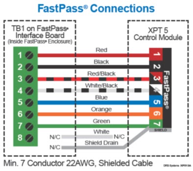
1. Verify the wiring is terminated properly.
a. Verify the wiring at the FastPass terminal block on the control module is terminated properly, according to the image below.
2. Verify the 48V LED on the control module is on.
a. If the LED is off, disconnect the FastPass terminal block from the control module, and then turn the XPT main power switch off for 10 seconds and then back on.
i.If the 48V LED on the control module turns on, there is likely a short in the FastPass wiring, enclosure, or reader - continue to troubleshoot the FastPass hardware according to the "AWID MPR-2010BR FastPass Reader - XPT 5" topic.
ii. If the 48V LED on the control module does not turn on, determine if the 48V LED on the power module is on.
If the 48V LED on the power module is off, the power module should likely be replaced.
If the 48V LED on the power module is on, the control module should likely be replaced.
3. Perform a communications loopback test.
a. Turn off the XPT at the main power switch.
b. Disconnect the FastPass terminal block from the control module.
c. Remove the wires from terminals 5 (RxD) and 6 (TxD), and temporarily cover each with insulating tape or wire nuts.
d. Place a jumper wire across terminals 5 and 6 on the FastPass terminal block.
e. Turn on the XPT at the main power switch.
f. When prompted, log in to security.
g. Navigate to the FastPass Reader screen in maintenance mode.
h. If the status indicates Loopback OK, there is likely a short in the FastPass wiring, enclosure, or reader - continue to troubleshoot the FastPass hardware according to the "AWID MPR-2010BR FastPass Reader - XPT 5" topic.
i. If the status does not indicate Loopback OK, the control module should likely be replaced.
White Water guide · Download PDF ↗