Overview
Product: XPT 5 Power Module (XP11060)
This topic describes the power module in an XPT 5 and XPT 5+.
*Note: The power module includes three industrial power supplies, power distribution board, alarm/interior light backup battery, 120V surge suppressor, and a heater assembly.
*Note: The power module is considered a "sealed" unit, meaning that we should not try to remove any protective covers or disassemble the module – individual components are not field-replaceable.
*Note: The 120VAC present indicator remains lit anytime power is provided to the power module from the site electrical system. This safety indicator will only turn off if power is removed by either turning off the breaker in the site’s electrical panel, or by disconnecting the incoming power connector from the front of the power module.
Pictures & COnnections
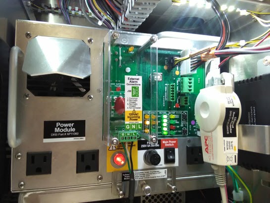
Front
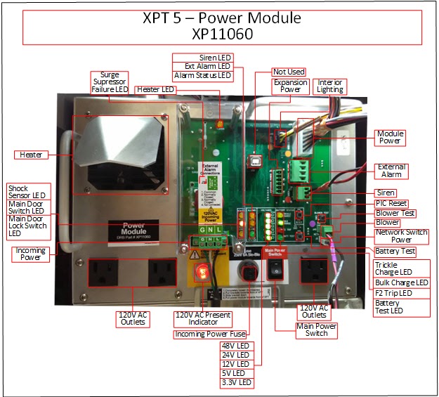
Connections Labeled
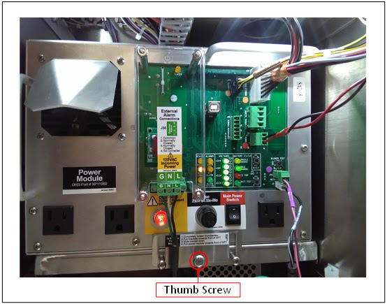
Serviceable Fasteners
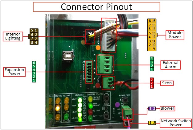
Connector Pinouts
Incoming Power
Pin Description
1 120V Line
2 120V Neutral
3 Ground
Expansion Power
Pin Description
1 For Future Use
2
3
4
5
6
Siren
Pin Description
1 N/O 12V Output
2 GND
3 Not Connected
External Alarm
Pin Description
1 Relay Output Common
2 N/C Relay Output
3 N/O Relay Output
4 Not Connected
Interior Lighting
Pin Description
1 Main Door Switch In 1
2 GND
3 GND
4 GND
5 Main Door Switch In 2
6 12V Lights
7 12V Lights
8 12V Lights
Module Power
Pin Description
1 GND
2 GND
3 GND
4 GND
5 GND
6 Shock Sensor In
7 Siren On
8 Main Door Lock In
9 48VDC
10 12VDC
11 24VDC
12 12VDC
13 24VDC
14 +12V Battery
15 External Alarm On
16 Main Door Switch Out
Blower
Pin Description
1 12VDC
2 GND
Network Switch Power
Pin Description
1 5VDC
2 GND
Troubleshooting
Turn off power to the XPT at the breaker panel before disconnecting the incoming power connector.
Turn off the XPT before modifying any power wiring connections.
An employee with security access must enter his or her employee information into the XPT after unlocking, but before opening, the main door. Failure to follow this procedure causes the alarm to sound.
Restart the XPT
1. Unlock the XPT main door. The security login screen appears.
2. Log in to security. The Main Status Screen appears.
3. Open the XPT main door.
4. Turn the power off using the switch on the front of the power module.
5. Wait a minimum of 10 seconds.
6. Turn the power back on.
The power module 12V, 24V, and/or 48V LEDs are off
1. If the 12V, 24V, and/or 48V LEDs are off, verify the 120V power light (Amber) is on.
a. The power light is off.
i. Verify the site power to the XPT is turned on.
ii. Verify the 8A 120V fuse near the power switch is not blown.
iii. Turn off the site power to the XPT and verify the screws on the incoming power connector are completely tightened.
*WARNING: Verify the site power to the XPT is turned off while touching/tightening the terminals screws!
b. The power light is on.
i. Cycle power to determine if any overcurrent protection needs to reset.
Turn the power off using the switch on the front of the power module.
Wait a minimum of 10 seconds.
Turn the power back on.
ii. Disconnect all devices from the power module and determine if the 12V, 24V and 48V LEDs turn on.
Turn the power off using the switch on the front of the power module.
Disconnect the module power harness, interior lighting harness, siren, air intake blower, PoE pass-thru network switch, and expansion power (if used) connectors from the front of the control module.
Turn the power on and observe whether the 12V, 24V, and 48V LEDs are on.
If they are off, replace the power module.
If they are on, turn the power off again and reconnect one of the devices, then turn the power on and observe whether the LEDs are on.
Repeat this process until one of the devices causes the power module LEDs to not turn on – indicating that device is faulty.
*Note: If the 48V LED turns off when the control module is connected, the FastPass connector should be disconnected from the control module, and the above process should be repeated to determine if the FastPass reader and/or wiring is faulty.
The power module 3.3V LED or 5V LED is off, but the 12V LED is on
1. Voltages LED location.
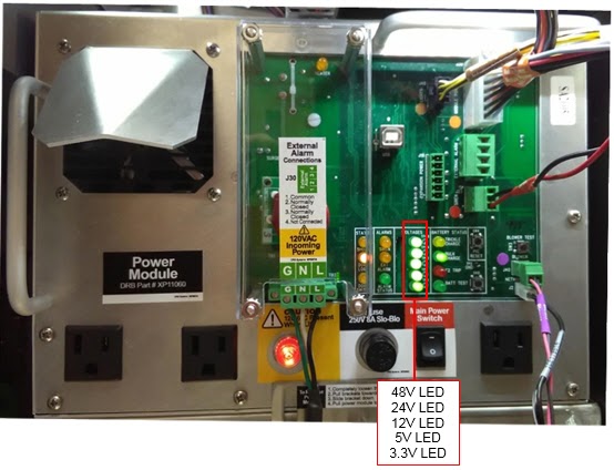
2. The power module is faulty and should be replaced.
The Surge Suppressor Failure LED is on
1. If the Surge Suppressor Failure LED is on, the power module will continue to operate, but it will not be protected from power surges.
a. The power module should be replaced.
The siren is activating when it should not be
1. Restart the XPT.
a. Unlock the XPT main door. The security login screen appears.
b. Log in to security. The Main Status Screen appears.
c. Open the XPT main door.
d. Turn the power off using the switch on the front of the power module.
e. Wait a minimum of 10 seconds.
f. Turn the power back on.
2. Determine if the Siren LED on the power module is on.
a. LED is on.
i. Determine if the Siren LED on the display module is on.
If it's on, troubleshoot the display module alarm circuitry.
If it's off:
Turn the power off using the switch on the front of the power module.
Disconnect the module power harness from the power module.
Turn the power switch on, and determine if the Siren LED on the power module is on.
If it is on, replace the power module.
If it is off, troubleshoot the display module alarm circuitry.
b. LED is off.
i. Verify the siren is connected to terminals 1 and 2 on the pluggable terminal block that connects to the power module.
ii. If the problem continues, the power module should likely be replaced.
The air intake blower is not operating when it should be
*Note: The blower will not turn on until the temperature inside the XPT reaches approximately 110F.
1. Press the Blower Test button on the front of the power module, and determine if the air intake blower turns on.
2. If it does not turn on, replace the air intake blower.
3. If it does turn on, the power module should likely be replaced.
The interior lighting is not turning on when the power switch is turned on and the main door is open
*Note: The interior lighting turns on when the main door is opened, and automatically turns off after approximately 15 minutes. Press and release the main door switch to turn the lights back on.
1. Open the Security Devices screen in maintenance mode.
2. Press and hold the main door switch and verify its status on screen changes from Now Open to Now Closed.
a. If the status doesn't change, troubleshoot the main door switch using the steps in this topic.
b. If the status does change, replace the interior lighting harness and light modules.
The interior lighting is functioning properly when the power switch is on, and improperly when the power switch is off
1. Allow the 12V battery inside the power module to fully charge by leaving the power switch on for at least 12 hours.
2. If after allowing the 12V battery to charge, the interior lighting still doesn’t function properly, consider replacing the power module.
The Main Door Switch is not indicating the proper status in maintenance mode when opened/closed
1. Verify the interior lighting harness is connected to the front of the power module.
2. Manually press and hold the main door switch and verify the main door LED on the front of the power module turns on.
a. LED turns on.
i. Verify the main door switch and the actuator bracket are making contact when the main door is closed.
If they are not, gently bend the actuator bracket into place.
b. LED does not turn on.
i. Temporarily touch a paperclip or jumper wire between the two terminals on the switch that connect to the harness.
If the LED turns on, the main door switch should be replaced.
If the LED does not turn on, disconnect the interior lighting harness from the power module, and temporarily touch a paperclip or jumper wire between pins 4 and 8 (top row) on the interior light connector on the power module.
If the LED turns on, the interior lighting harness is faulty and should be replaced.
If the LED does not turn on, the power module should likely be replaced.
c. LED turns off when depressed, and on when not depressed.
i. Verify the connectors from the interior lighting harness are connected to the two terminals on the main door switch marked COM and NO.
3. If the power module main door LED turns on and off when it should, but the Main Door Switch status in maintenance mode doesn’t change, verify the main door LED on the display module mirrors the main door LED on the power module.
a. If it does not, the display module should likely be replaced.
Replacing
*WARNING: Turn off and lockout the main breaker that supplies power to the XPT before removing the power module. Failure to do so could result in equipment damage, electrocution, or death!
*All below steps should be completed by a member of the facilities team, DO NOT ATTEMPT any of the below steps yourself.
Tools needed
Precision flat head screwdriver
1. Turn off the XPT.
a. Unlock the XPT main door. The security login screen appears.
b.Log in to security. The Main Status Screen appears.
c. Open the XPT main door.
d. Turn the power off using the switch on the front of the power module.
2. Turn off the main breaker that supplies power to the XPT.
a. Locate the main breaker that supplies power to the XPT and turn it off.
*WARNING: Failure to do so could result in equipment damage, electrocution, or death!
b. Protect the breaker with a lockout/tagout to prevent someone from accidentally turning it on.
3. Remove the incoming power connector from the power module.
a. Completely loosen the (2) flat head screws on each side of the incoming power connector using a precision flat head screwdriver.
b. Pull the incoming power connector away from the power module.
4. Disconnect all remaining cables from the power module.
a. Disconnect all cables from the distribution board on the power module.
b. Disconnect any external power supplies or cords from the (3) 120VAC outlets on the front of the power module.
5. Remove the power module from the XPT.
a. Completely loosen the thumb nut on the front of the retaining bracket.
b. Pull the retaining bracket towards the front of the XPT and then slide it down.
c. Remove the power module by pivoting the left side of the power module towards the right wall of the XPT, and then sliding it towards the front of the XPT.
6. Install the replacement power module.
a. Slide the replacement power module onto the shelf bracket, until the retaining pins engage into the back of the power module.
b. Slide the retaining bracket upwards and align the retaining pins with the front of the power module.
c. Tighten the thumb nut on the front of the retaining bracket with your fingers, until snug.
7. Reconnect the incoming power connector to the replacement power module.
a. Tighten the (2) screws on each side of the connector using a precision flat head screwdriver.
8. Reconnect all remaining cables to the power module.
a. Reconnect all cables to the distribution board on the power module.
b. Reconnect any external power supplies or cords to the (3) 120VAC outlets on the front of the power module.
9. Turn on the main breaker that supplies power to the XPT.
10. Turn on the XPT and lock the main door.
a. Turn the power on using the switch on the front of the power module.
b. Close and lock the XPT main door.
11. Verify the power supply is installed properly.
a. Verify the power LEDs on the following components are on:
ii. Control module
ii. Bill dispenser
iii. PoE pass-thru network switch
b. If any components are not receiving power, verify all cables are properly connected to the power module.
White Water guide · Download PDF ↗